Titanic Airline's B-29
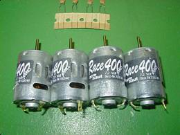
This balsa sheeted, white foam kit is such a masterpiece that I almost hate to put it together. It will certainly be a joy to build and fly. A number of decisions must be made before assembly begins. Power and control options are the two major ones. For power I will be using 4 speed 400 motors wired in parallel to a single 40 amp Kotronic ESC with BEC. Electrons will be stored in a single 7cell RC2400 pack. Control of the airframe will be via elevator and ailerons. No landing gear or rudder control, either would add complexity, cost, and weight with no gain in flight performance.
I must thank Bernard Cawley for his help on this project. He helped me attain this kit and also guided me to a proper ESC to control the motors. Bernard and all the fine patrons of E-Zone helped sort out a power system that should fly this aircraft beautifully.
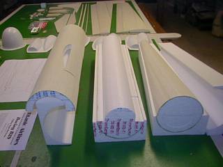
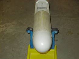
A look at the project in
"The Bones"
And here we go!!! 10-14-01
7.2 Volt Speed 400 motors
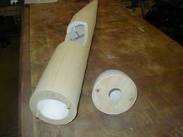
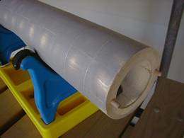
The 4 fuselage parts glued together. They trap the 2 wing mounting tubes in place.
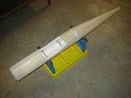
Nose ring and guide dowels in place. Nosecone is drilled to match and will be held in place via rubber band.
Nose cone test fit and wing attachment tubes epoxied to fuse sidewalls.
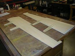
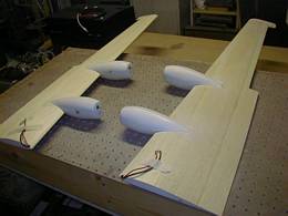
The motor mounts all built up and the slots cut into the wing where they glue in place. Make sure to build in the proper downthrust when assembling the mounts, I nearly built mine flat by accident. They are only being test fit to the wing at this time.
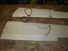
A soldering gun was used to melt the foam a the front edge of the wing so that the wiring could be layed in place before the LE stock was glued in place. Now the LE is sanded to the proper shape, cuts will be made in the LE material so the mounts can be slid in and glued in place.
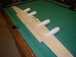
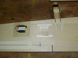
The motor mounts are in place and the wing has been cut out for the aileron servos. The mini servo are wrapped with tape and then glued to the 1/32 ply, only the end of the servo arm will be exposed.
There is no doubt that cutting out the vacum formed engine nacelles are the most time consuming. Nibble away a very little bit at a time until they fit the wing.
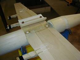
Once the wing halves are joined and the center section glassed, It is time to fit the wing fairing to the wing / fuse. The fairing is then glued to the wing. Holes must be drilled in the fairng to gain access to the wing bolts. I made some paper guide tubes for the bolts to slip down through.
Adding these bolt tubes, mounting servos, etc is all up to the builder to figure out...not a beginners kit.
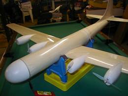
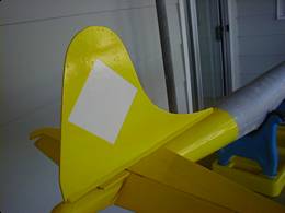
And it is ready for covering on Oct. 28th. The tail group will be covered before gluing it to the fuselage. The bottom of the wing is covered at this point. 2 weeks have gone by quickly.
Short break in the action for treatment of some health concerns.. will continue on shortly 10-29-01 RLL
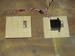
OK, we are back again. Here are the 1/32 ply plates that the mini servos for the ailerons are glued to. The servos were wrapped with taped before gluing to the ply.
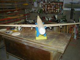
This shows the wings ready to join. All is in place except for the ailerons which have to be covered first.
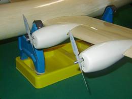
I love these props and adapters by Graupner.
Via Hobby Lobby
Covering is Oz Cover, a paintable clear covering from my friends down in Australia. It irons on quickly and takes paint very well. Contact me for availablity. It is a great and unique covering.
Notice the transparant props... Picture was taken with Olympus D-400 camera while motors were running approx. 1/2 speed.
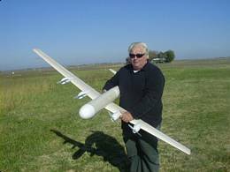
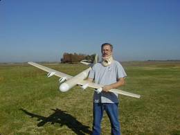
Ready to go and at the field. My friend and talented test pilot Ross.
For all of you that either don't know me, or have forgotten. This is RandyL. ( My Login name on many forums )
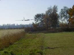
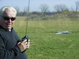
Ross's great piloting skills made it all look easy on take off. I hand launched it for Ross so no pics of that. Instead here is a photo of a low pass while determining the proper landing atitude.
The motor, ESC, and battery choices were perfect. I thank you all for your input, it is perfect.
Touchdown.....after a perfect flight! We are very happy!
Next will be paint and markings, then it will be even more outstanding. Thanks for the fantastic flight Ross.
First flight, Nov. 4, 2001.. 22 days after opening the kit box.
specs at top of page
Click on image for full size awesome pic!
Even has a menacing shadow
Thanks to Kepople from E-Zone for editing out an errant transmitter ant. in the above photo.
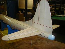
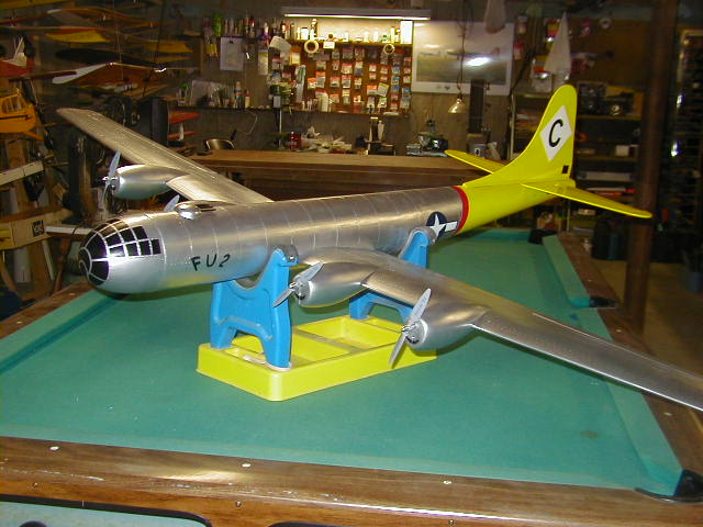
Now for the finish work...
Panel lines are taped off. I'm using 1/16th and 1/32 tape. It is what I have laying around, different colors, brands and sizes. It doesn't matter
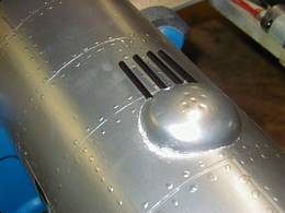
Once taped up, I primered it with laquer auto primer and then sanded lightly until the tape showed thorugh. Peel the tape off and start putting on the "glue" rivets.
Next is the start of the color coat. A light paint job is needed to keep weight down and not fill in the panel lines.
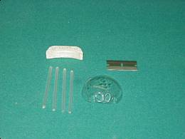
While things were drying I made up the upper turret from balsa, nyrod tubing, and a piece of plastic that I hot formed over a salt shaker top.
Sorta looks like 4 50 cals. This will be the only turret as this aircraft belly lands, the bottom must be kept smooth.
To take from one of the modeling laws of the great scale modeler Dave Platt. " It will never be finished but I am done working on it."
The above photo was taken 5 days after the test flight.
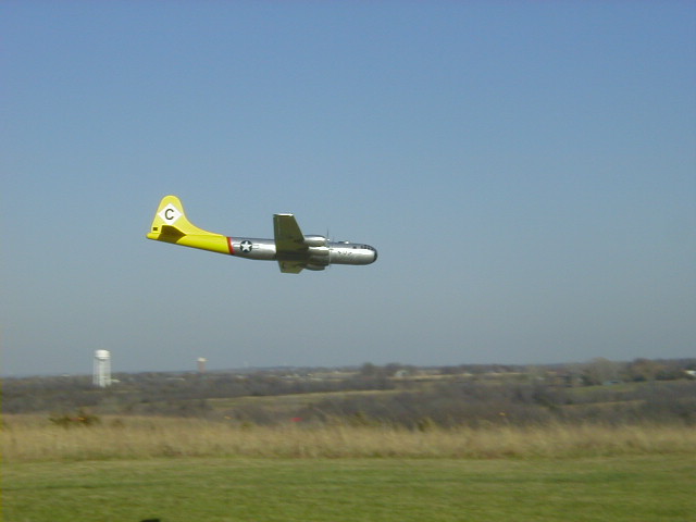
The photo below was taken on Veterans Day. November 11, 2001. Exactly one week after the initial test hop.
It looks so much better now....and flys great!
These kits are currently out of production. You will have to find them in stock at hobby shops
Oz Cover products can be purchased at A&J Aviation
here in the United States. Contact me concerning shipment world wide.
Click here to view extra pictures of the building process
Large, slower loading pics
